AN-009 · Embedded & Robotics · Finished
Started Jul 2023
An 8-bit CPU on the bench
1.0Abstract
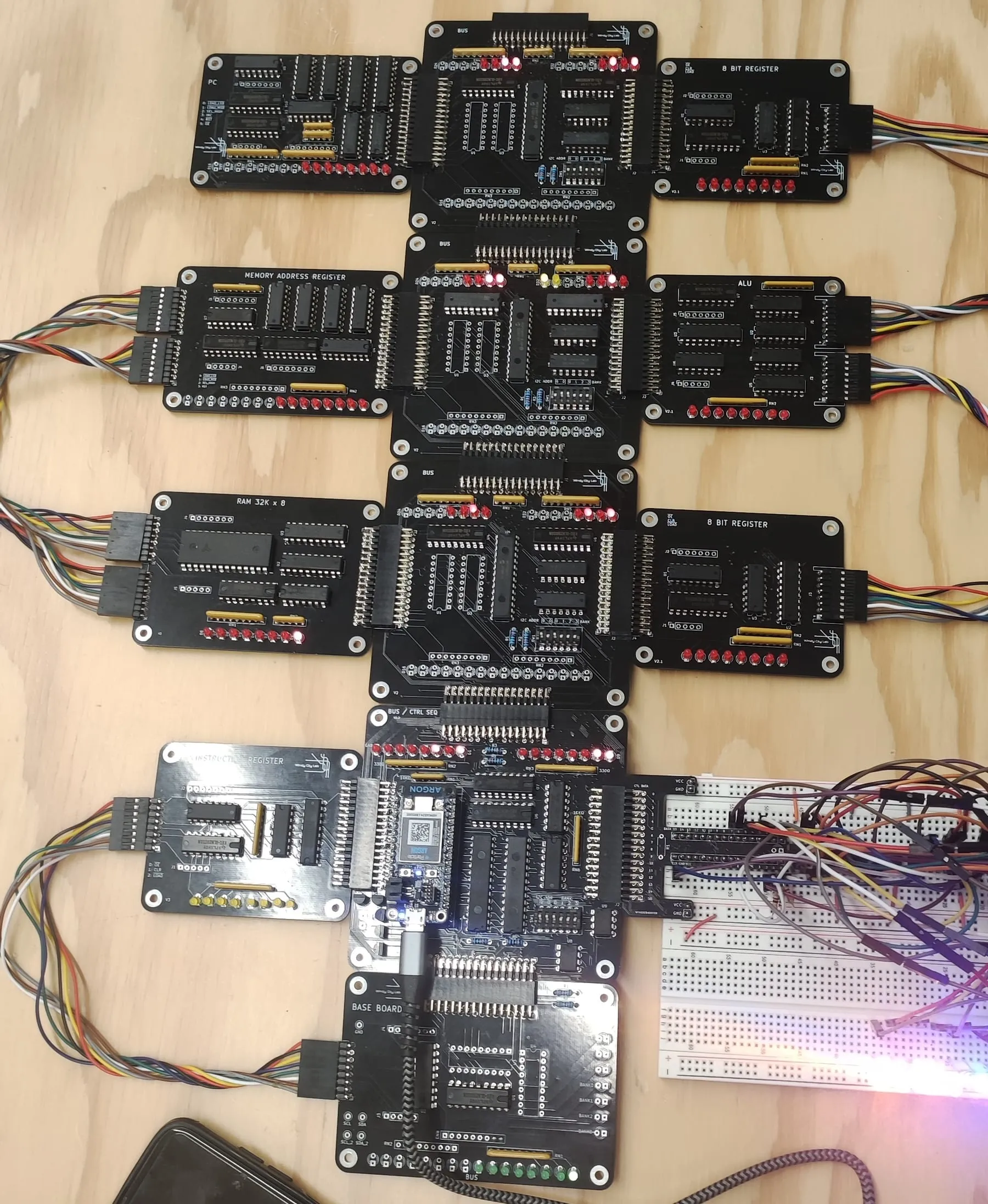
I built this over three weeks at a summer residency at Windy City Labs: an 8-bit CPU on a bench full of logic boards, with a 16-opcode instruction set and a Python assembler, checked on a logic analyzer. It runs Fibonacci, slowly.
At a glance
| Parameter | Value |
|---|---|
| Status | Finished |
| When and where | Summer 2023, three weeks at Windy City Labs, Northwestern CTD |
| Built with | Discrete logic boards, an EEPROM burner, a Python assembler, an oscilloscope and a logic analyzer |
| Boards | Program counter, bus boards, two 8-bit registers, memory address register, ALU, 32K×8 RAM, instruction register, bus / control sequencer, base board |
| Instruction set | 16 opcodes covering ALU, branch, memory and I/O; the assembler has macros for loops and immediate constants and emits hex for the EEPROM burner |
| Proof | Oscilloscope and logic-analyzer traces of the micro-instruction sequences; it runs Fibonacci, an LED chaser and a mini calculator |
Why build a CPU out of chips
After this, nothing about a microcontroller is magic: an instruction fetch, a bus, a flag register deciding a branch. All of it was wired by hand and watched on a logic analyzer.
Hardware
- An 8-bit data bus connecting a program counter, two general-purpose registers, a memory address register, an ALU, a 32K×8 RAM, and an instruction register, one board each, chained across a set of bus boards and a base board.
- A custom instruction set of 16 opcodes covering ALU operations, branches, memory access and I/O.
- A bus / control sequencer board that steps each instruction through its micro-operations.
Tooling and validation
- A Python assembler that emits hex for the EEPROM burner, with macros for loops and immediate constants to speed up prototyping.
- Oscilloscope and logic-analyzer sessions captured micro-instruction traces, which is how the propagation delay and debounce timing got tuned.
Teaching it
Lightning talks to other cohorts on opcodes, addressing modes, and why the flag register matters for branching; lab notes and test programs (Fibonacci, an LED chaser, a mini calculator) so the next students can extend the platform instead of rebuilding it.
Running it
Below is a small accumulator machine of the same shape (nine instructions, sixteen bytes) running Fibonacci the way the bench machine did. Step one instruction at a time to watch the accumulator, the flags and the program counter move, or run it to completion; it halts on the first 8-bit overflow, which is what the boards on the bench do too. The bench ISA had 16 opcodes; wiring the real table in is the next step.
What’s next
Wiring the real opcode table and the assembler output into the simulator above, so it runs the same hex the EEPROM burner did.