AN-001 · Embedded & Robotics · In progress
Started Jul 2026
A $3,000 haptic controller became a $300 board
1.0Abstract
At CMU’s Microdynamic Systems Laboratory I replaced the desktop side of the controller of a 6-DOF magnetic levitation haptic device (a legacy QNX PC and its PCI DAQ cards, in a full ATX case) with a $300 STM32H7 board. That meant porting the firmware off QNX and driving AD7606 and LTC2688 converters over SPI with DMA within a 15 µs budget. The linear amplifiers are still the legacy units; their replacement is designed, not yet built. I also wrote a driver so the device’s force feedback works inside the SOFA simulator. Driving the lab’s ballbot with it is written up separately under Shmoobot.
At a glance
| Parameter | Value |
|---|---|
| Status | In progress. Prototype, not production |
| When and where | Jul 2026 – present, Microdynamic Systems Laboratory, Carnegie Mellon |
| My part | Undergraduate researcher: the controller, its firmware, the amplifier replacement design, and the SOFA integration |
| Built with | STM32H7; AD7606 ADC and LTC2688 DAC over SPI with DMA; a DRV8262 driver board in KiCad; SOFA |
| Before | A legacy QNX real-time PC with PCI DAQ cards, in a full ATX case: about $3,000. The linear amplifiers are separate and still in use |
| After | One ~$300 STM32H7 board in place of the PC and DAQ cards, with ~2× the compute and a 15 µs sensor-to-actuator budget |
| Amplifier | Still the legacy linear units, about $3,000 on their own. A replacement is designed, not built: a 7-channel DRV8262 board with INA240 current sensing, in KiCad; a switching PWM stage in progress |
| On show | Robotics & AI Discovery Day, Sep 16 2026; IROS 2026, Sep 27 – Oct 1, at the Butterfly Haptics table |
The setup
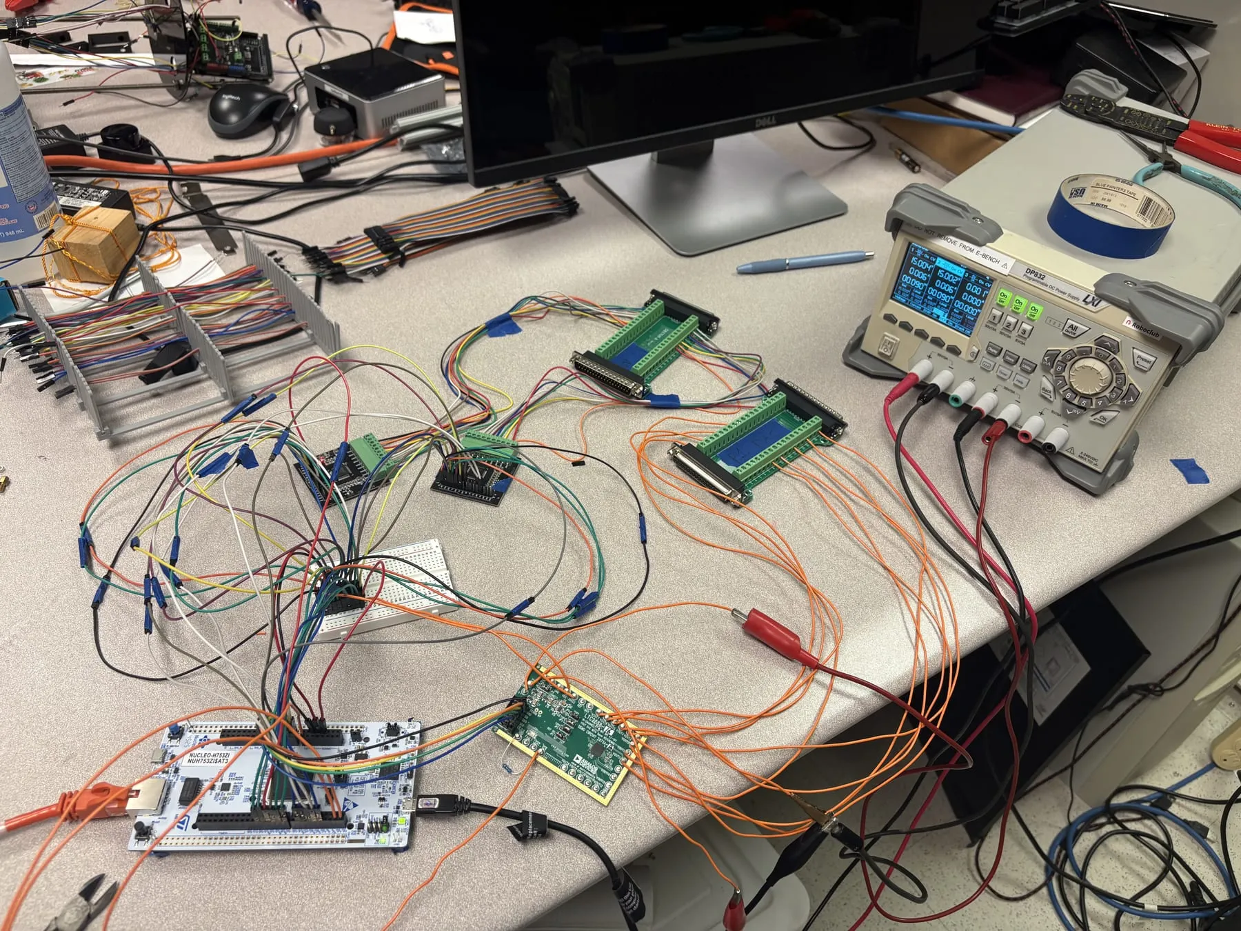
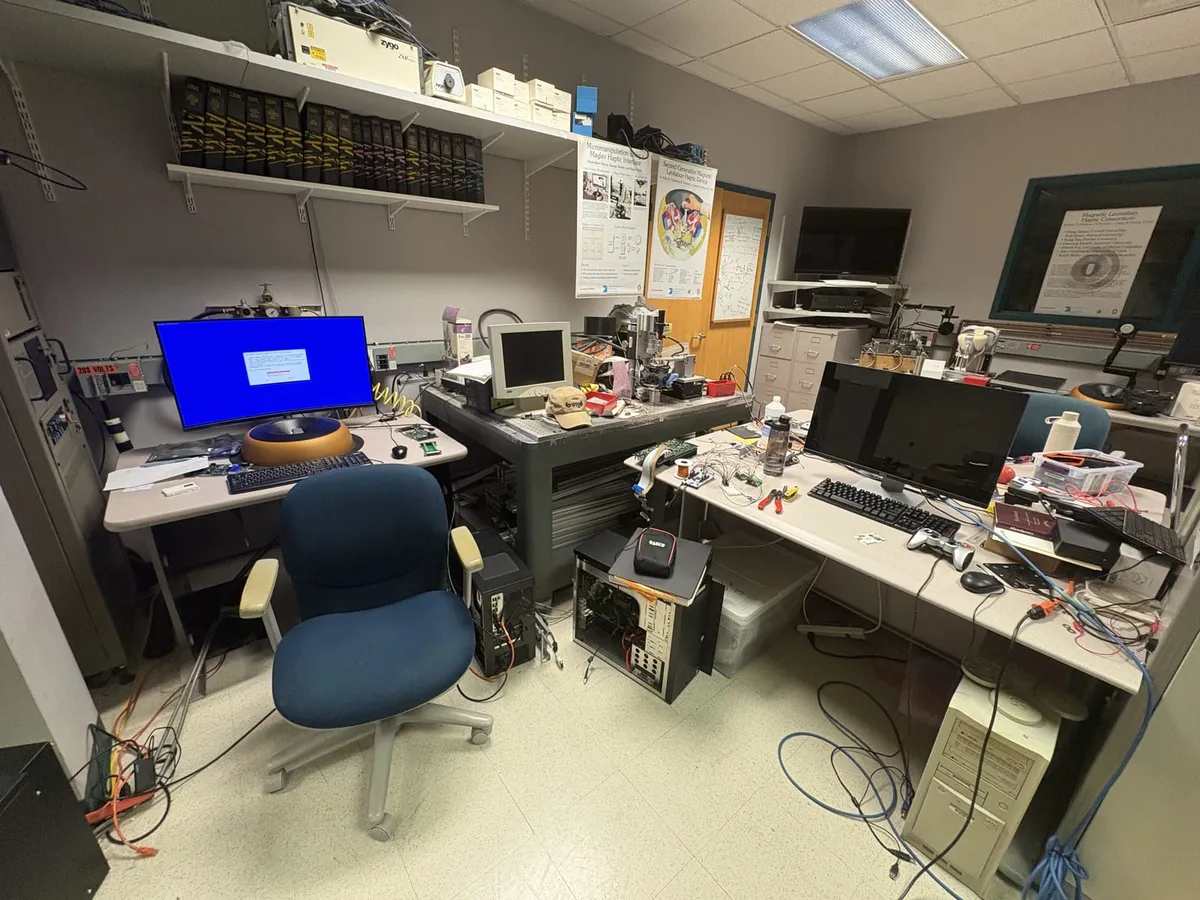
The lab’s maglev haptic device floats a handle on magnetic fields and pushes back on your hand with whatever force the software asks for, in six degrees of freedom. The controller that closed that loop lived in a full ATX PC case: a legacy QNX real-time machine and PCI DAQ hardware, driving the device through linear amplifiers that are still in use. One note on the photographs: the controller design belongs to the lab, so they show the bench, the device and the demos rather than the board in detail.
The PC became a board
The main result is that the PC side of the control stack, a $3,000 desktop machine with its DAQ cards, became a $300 board, as a modular design that can be swapped and extended. The linear amplifiers are not in that figure: they are the legacy units still, about $3,000 on their own, and their replacement is designed but not built. The size collapse is real but unmeasured, so this page describes the change rather than claiming a multiplier.
   position sensors (6-DOF maglev device)
              │
              ▼                       ┐
   AD7606 ADC ─ SPI with DMA          │
              │                       │
              ▼                       │  15 µs
   STM32H7 (Cortex-M) ─ servo loop,   │  sensor-to-
   firmware ported off QNX            │  actuator
              │                       │  budget
              ▼                       │
   LTC2688 DAC ─ SPI with DMA         │
              │                       │
              ▼                       │
   amplifier ─ legacy linear units,   │
   replacement designed, not built    ┘
              │
              ▼
   flotor coils → handle → sensors
Why the budget is fifteen microseconds
A magnetically levitated flotor is open-loop unstable: it falls unless the loop catches it. That is what the sensor-to-actuator budget buys, and it is why the number is a hard constraint rather than a target. Drag the latency below and watch the loop lose it. The model loses the flotor at roughly 110 µs; the real device has six coupled axes, sensor noise and amplifier bandwidth that the model leaves out, which is why the budget sits well inside that edge.
This is an idealized single-axis model with delayed state feedback. It shows why latency matters; it is not a measurement of the device, and no loop figure on this page is measured yet.
Firmware
I ported the firmware off the legacy QNX machine onto the STM32H7, replacing the PCI DAQ path with an AD7606 ADC and an LTC2688 DAC driven over SPI with DMA, and budgeted a 15 µs sensor-to-actuator path against the legacy loop. The STM32 gives roughly 2× the compute throughput of the QNX software.
The amplifier
The linear amplifiers have not gone. They are the legacy units still, and at about $3,000 on their own they are the next thing to replace. I designed the replacement as a modular unit: a 7-channel DRV8262 motor-driver PCB in KiCad with INA240 current sensing and 2512 shunt resistors. It is designed but not yet fabricated. A switching PWM-mode amplifier for better efficiency and a smaller footprint is in progress. An earlier interim step used a DB37 breakout board to drive the original amplifier while the rest of the stack was being moved.
Haptics in the simulator
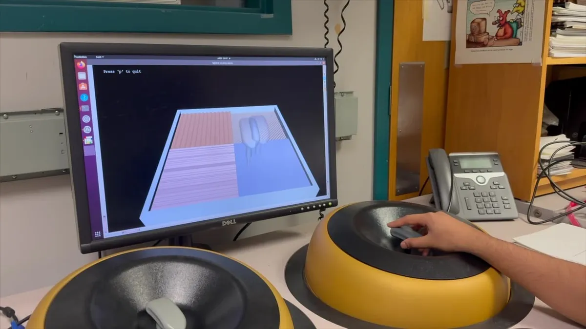
The device is programmed against the MLHI API. I wrote a driver that exposes MLHI to SOFA, a separate simulation framework, so haptic force feedback runs inside the simulation loop (you can feel the simulated scene), updated 8 demos, and debugged the SOFA haptic drivers for instrument velocity in collision response and rotational force output.
The ballbot
The same device later drove the lab’s ballbot, the Shmoobot, with force feedback, so the operator’s hand gets information back from the robot instead of only sending commands to it. That work is written up separately under Shmoobot.
What’s next
The switching PWM amplifier, and fabricating the DRV8262 board. In September I’m demoing and presenting the haptic-device work at CMU’s Robotics & AI Discovery Day (Sep 16), and demoing the SOFA integration and demos at the Butterfly Haptics table at IROS 2026 (Sep 27 – Oct 1).